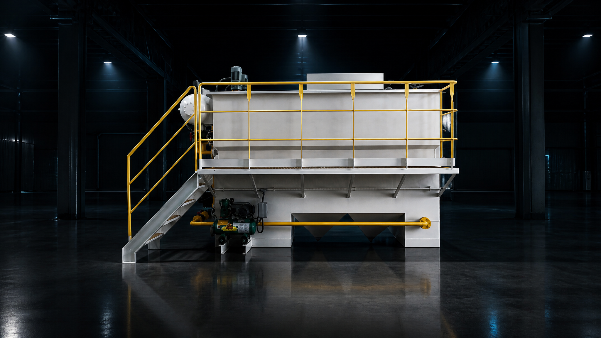
A dissolved air flotation unit sized on the annual average flow and load of a food processing plant will be overwhelmed within weeks of commissioning. The reason is straightforward: food plants do not discharge at steady state. Cleaning-in-place cycles, batch changeovers, product line flushes and shift-end washdowns create short-duration load spikes that can be three to five times the daily average in terms of fats, oils and grease concentration.
Sizing a DAF for average conditions and then operating it through these peaks is the most common cause of surcharge notices from the municipal authority.
DAF in Food Processing — Key Facts
- Typical FOG peak factor
- 3–5× daily average during CIP and shift-end washdown
- Hydraulic retention time
- 20–40 minutes at design peak flow
- Recycle ratio
- 25–50% of inlet flow for adequate bubble generation
- Chemical dosing
- Coagulant + flocculant; dose must track load, not flow alone
- Sludge (float) solids
- 3–8% dry solids depending on product type
Engineering Hub: get this sized for your plant
Describe your goal, effluent limit or sludge volume and receive a technology shortlist plus a sizing proposal – by email, no phone call required.
Understanding the load profile of a food plant
Before specifying a DAF, map the discharge profile over at least two full production weeks. The key events to capture are:
- CIP cycles: cleaning-in-place discharges are typically short (30–90 minutes) but highly concentrated in FOG, COD and sometimes caustic or acid. They arrive at predictable times if the production schedule is fixed.
- Batch changeovers: switching between product lines generates a flush of residual product that can spike COD by a factor of four or more.
- Shift-end washdowns: floor and equipment washing at shift end concentrates solids and FOG into a short hydraulic peak.
The design peak flow for the DAF should be the maximum hourly flow observed during the campaign, not the daily average divided by 24.
3–5×
Typical FOG concentration factor during CIP vs. steady-state production
20–40 min
Hydraulic retention time needed at peak flow for effective flotation
25–50%
Recycle ratio range for adequate dissolved air supply
Chemical dosing that tracks load, not flow
The most common operational mistake in food-industry DAF systems is dosing coagulant and flocculant proportionally to flow. During a CIP discharge, the flow rate may be similar to normal production, but the FOG and COD load is three to five times higher. A flow-proportional dosing system will underdose during the peak and overdose during steady-state production.
Load-proportional dosing — triggered by an inline turbidity or COD sensor — is the correct approach. The sensor detects the rising load and increases chemical dose before the peak reaches the flotation zone. This requires a short buffer volume (a feed tank or inlet channel) between the discharge point and the DAF inlet to give the dosing system time to respond.
Buffer Volume Before the DAF Inlet
A buffer tank or inlet channel with 10–20 minutes of retention at peak flow gives the chemical dosing system time to respond to load spikes before they reach the flotation zone. Without this buffer, a CIP discharge can pass through the DAF underdosed and appear in the effluent as a visible FOG plume.
Sludge (float) management
Food-industry DAF float is typically 3–8% dry solids and has a high organic content. It must be removed continuously or at frequent intervals — allowing float to accumulate on the surface degrades effluent quality and can cause re-entrainment of solids into the treated water.
The float removal rate should be matched to the production schedule: higher frequency during and immediately after CIP cycles, lower frequency during steady-state production. Automated skimmer control linked to the production schedule is a practical solution for larger plants.
DAF Commissioning Checklist for Food Plants
- Map the full discharge profile over two production weeks before sizing
- Set design peak flow from maximum observed hourly flow, not daily average
- Install inline turbidity or COD sensor for load-proportional chemical dosing
- Provide 10–20 minutes buffer volume between discharge and DAF inlet
- Set skimmer frequency to match production schedule, not a fixed timer
- Verify recycle ratio at peak flow — reduce inlet flow if necessary to maintain ratio
- Sample effluent during first CIP cycle after commissioning to confirm compliance
How do I size a DAF for food processing wastewater with variable loads?+
Size the DAF hydraulically for the maximum observed hourly flow from a two-week measurement campaign, not the daily average. Size the chemical dosing system for the peak FOG and COD load observed during CIP cycles. Include a buffer volume of 10–20 minutes at peak flow between the discharge point and the DAF inlet to allow load-proportional dosing to respond before the peak reaches the flotation zone.
Why does my DAF effluent deteriorate during cleaning-in-place cycles?+
CIP discharges arrive at three to five times the steady-state FOG and COD concentration. If the chemical dosing system is flow-proportional rather than load-proportional, it will underdose during the CIP peak. The result is incomplete floc formation and FOG carry-over into the effluent. Installing an inline turbidity or COD sensor and switching to load-proportional dosing typically resolves this within one production cycle.
What COD surcharge reduction can a correctly sized DAF achieve in a food plant?+
A DAF sized and operated for peak loads typically removes 70–90% of FOG and 40–60% of COD from food processing wastewater. The exact reduction depends on product type, chemical dosing optimisation and whether the DAF is followed by a biological stage. Surcharge relief is most significant for plants with high-fat products such as dairy, meat processing or edible oil refining.
Equipment we supply for this
Engineering Hub: get this sized for your plant
Describe your goal, effluent limit or sludge volume and receive a technology shortlist plus a sizing proposal – by email, no phone call required.