Engineering Hub: get this sized for your plant
Describe your goal, effluent limit or sludge volume and receive a technology shortlist plus a sizing proposal – by email, no phone call required.
Key Facts
- Label
- Value
- Existing basin reuse
- Often feasible if freeboard, geometry, and structural reserve are sufficient
- Primary engineering focus
- Hydraulic loading, structural capacity, inlet and outlet arrangement, maintenance access
- Typical retrofit objective
- Increase tertiary treatment capacity without constructing new tanks
- Critical first checks
- Available footprint, water level profile, beam and slab load reserve, headloss margin
- Common fit-for-purpose options
- In-basin disc filter, cloth media filter, lamella separators
- Decision point
- Feasibility should be proven by survey, calculations, and interface coordination before procurement
95%
of retrofit success depends on correct hydraulic and interface assessment before equipment selection
0.5-1.5 m
typical remaining freeboard that may still be usable, subject to local geometry and surcharge risk
1.5-3.5 kN/m²
indicative additional structural allowance often reviewed for service platforms and equipment zones
10-40%
potential capacity increase when a basin is successfully repurposed for tertiary filtration duty
2-6 weeks
common duration of a serious feasibility study including survey, calculations, and layout validation
Engineering risk note
Do not assume that a basin can accept a disc filter simply because it is “dry enough” or visually intact. Structural adequacy must be checked against the actual load paths, including concentrated loads from support frames, maintenance access points, and dynamic forces from filling, draining, and backwash cycles. Hydraulic feasibility must also include extreme conditions such as peak wet-weather flow, temporary downstream blockage, and the available emergency overflow path. If any of these conditions are unverified, the retrofit should be treated as provisional rather than executable.
Feasibility assessment sequence
- 1. Confirm as-built geometry and invert levels, because outdated drawings often misrepresent the true tank dimensions and available hydraulic grade line.
- 2. Measure the current operating water levels and compare them to the disc filter vendor’s minimum submergence, maximum submergence, and headloss requirements.
- 3. Calculate hydraulic loading at average, peak dry-weather, and peak wet-weather conditions to verify whether the basin can accept the full treatment duty.
- 4. Review the inlet and outlet configuration to identify dead zones, short-circuiting, vortex formation, and the need for flow distribution baffles.
- 5. Check structural capacity of slabs, beams, walls, and existing penetrations for static and operational loads, including localized equipment reactions.
- 6. Verify maintenance logistics, such as removal routes, crane access, lifting height, and space for cleaning or replacement without dismantling adjacent assets.
- 7. Evaluate compatibility with upstream and downstream processes so that bypass, backwash, and filtrate return do not compromise plant performance.
- 8. Document all assumptions in a decision package before ordering equipment, because late design changes are far more expensive than a rigorous pre-order review.
retrofit existing basin with disc filter | upgrade wastewater plant without new tanks | in-basin cloth media filter installation | capacity upgrade existing clarifier+
These options can all be viable, but the right solution depends on the basin geometry, hydraulic head, and structural reserve. A disc filter retrofit is usually best when the existing basin can provide the necessary submergence and clean-water path. A cloth media filter installed in-basin may suit some layouts, while a horizontal cloth filter or lamella separator may work better where access or headloss is limited. The feasibility study should compare each option against the same hydraulic and structural criteria.
How do we know if the existing basin is structurally strong enough for retrofit use?+
The check begins with as-built records, concrete condition surveys, and a load path review. Engineers then compare the imposed loads from the filter units, walkways, maintenance equipment, and water movement against the capacity of slabs, beams, walls, and foundations. If documents are incomplete, nondestructive testing and localized verification openings may be required. The goal is to confirm that the basin can safely carry both normal operation and maintenance scenarios.
What is the biggest mistake in a capacity upgrade existing clarifier project?+
The most common mistake is treating the basin as a simple empty shell and ignoring hydraulic interfaces. If inlet energy is too high or outlet conditions are poorly controlled, the filter will be forced to operate under unstable flow distribution, which reduces performance and increases maintenance. Another frequent error is ordering equipment before confirming level constraints, because a few centimeters of mismatch can eliminate an otherwise promising retrofit. A detailed pre-order assessment avoids both problems.
Equipment we supply for this
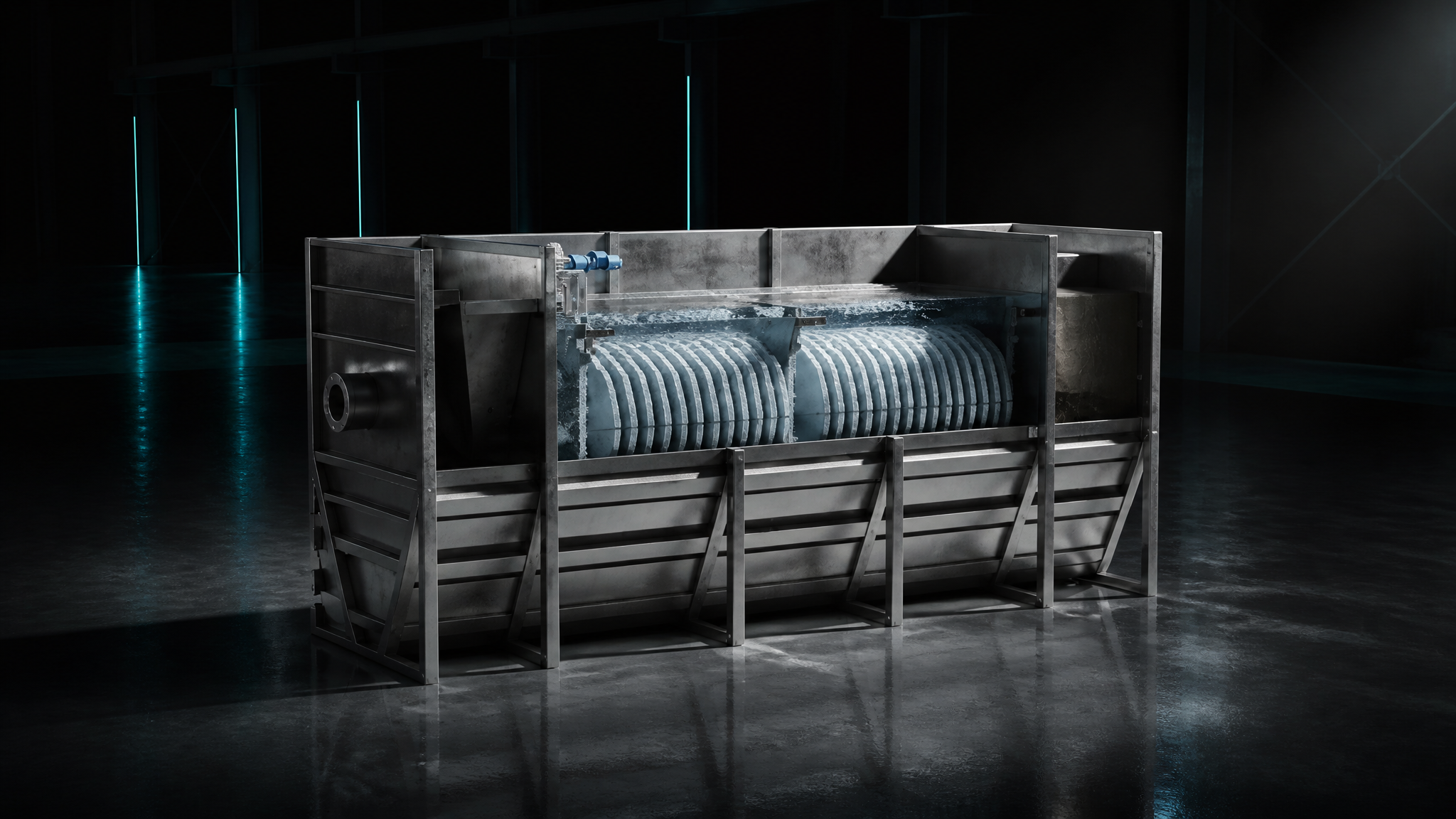
Horizontal Pile Cloth Disc Filter
Horizontal design for high flow rates and easy maintenance access
Technical dataLamella Separators
Maximum settling area on a minimal footprint
Technical dataHorizontal Pile Cloth Disc Filter
Horizontal design for high flow rates and easy maintenance access
Technical dataEngineering Hub: get this sized for your plant
Describe your goal, effluent limit or sludge volume and receive a technology shortlist plus a sizing proposal – by email, no phone call required.